
One of the things I struggled to get my head around when I first started this exercise was how something like a memory bus would work. How could you receive a set of inputs and use them to indicate which of several outputs (or memories) you wanted to read?
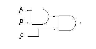
As a simple example let’s say we have two light bulbs A and B controlled by separate switches. We would want to use a third switch S and light bulb C. If switch S is off bulb C would be in the same state as bulb A but if the switch S is on it would be in the same state as light bulb B.
The answer (one answer?) is a multiplexer. In logic terms C is on (True) if A is on and S is off OR B is on and S is on. C = (A AND NOT S) OR (B AND S). That is a one-bit multiplexer as the switch S only has two states. One bit selects from two input channels.
If we use two switches, S1 and S2, we have four possible states so we can actually read any one of four inputs D0, D1, D2 or D3 – ie a 4-channel multiplexer.
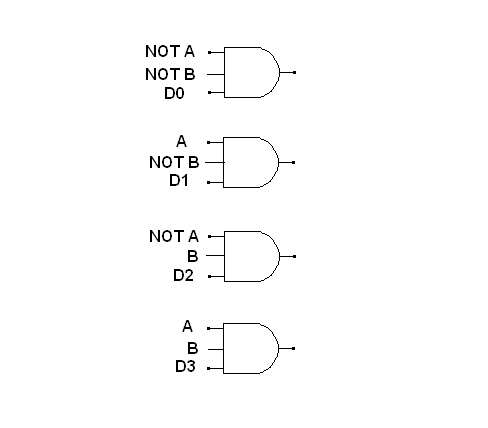 Only one of these three-input ANDs can produce a True output.
I didn’t have any three-input ANDs but it is easy to combine two two-input ANDs to make the equivalent.
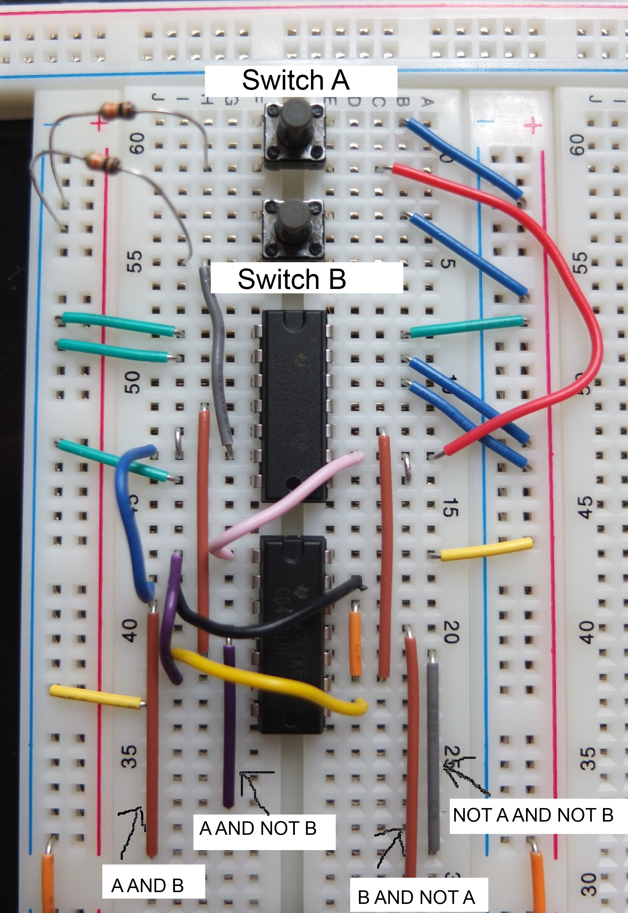
 So in the partial breadboard circuit below I’m using two NAND gates in a 4011 to produce inverted versions of the two inputs. The inputs are held low representing binary state 00. The second chip is a 4081 (quad two-input AND) which I’m using to produce all four combinations of A/NOT A and B/NOT B. I’ve labelled a few things to make this clearer (click on the image to enlarge if necessary).
 I’ve forgotten the decoupling capacitor at this stage but have tested each of the four switch settings to make sure they are working as expected. The next stage is to set up the four inputs we want to be accessing. I’ve used a bank of dip switches for the inputs so the state of each of the first 4 dip switches is ANDed (via another 4081) with one of the four combinations mentioned above and the result of the four ANDs passed to the transistor controlling the LED. (If I had one I could have used a 4-input OR or XOR to receive the four signals.)
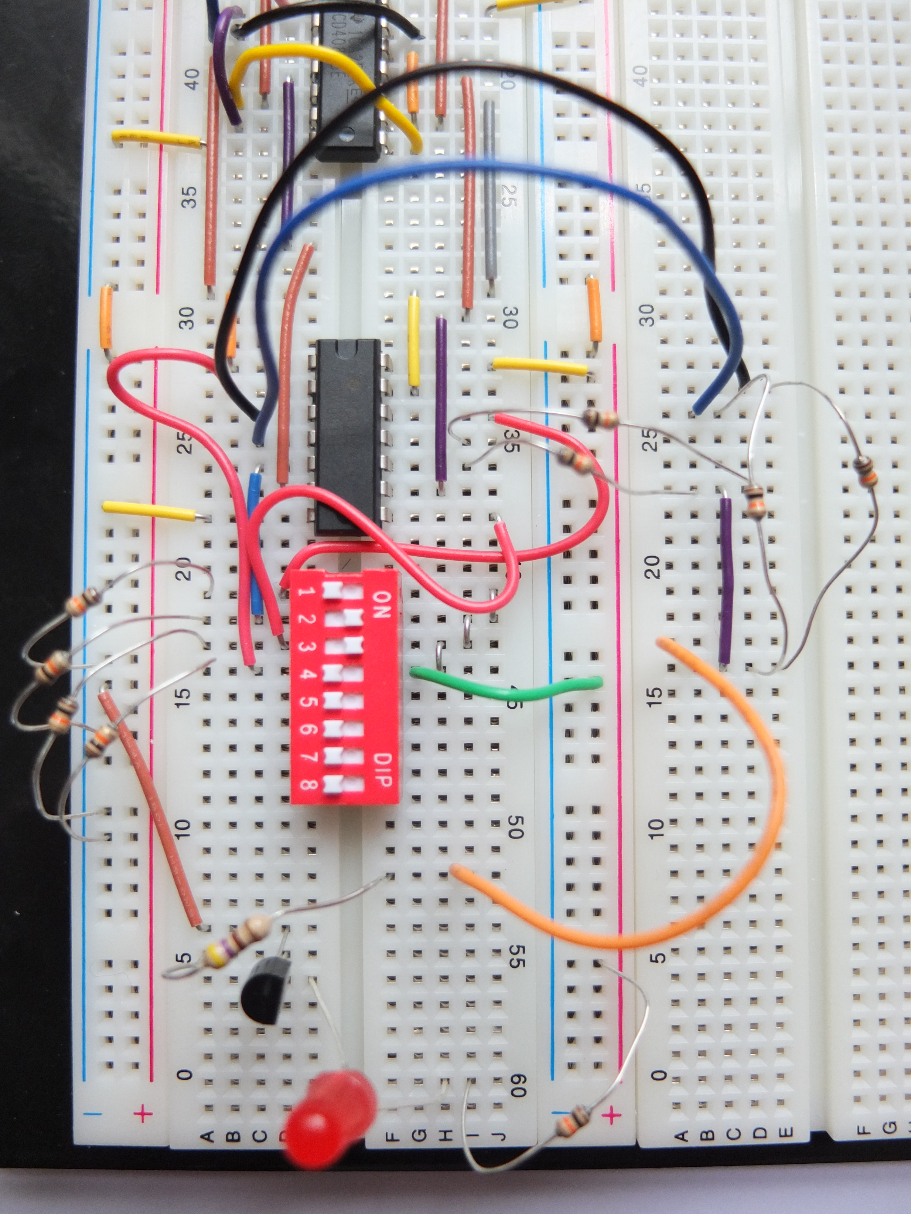 So what this gives us is an LED that indicates the state of one of the four dip switches according to the combination of switches pressed at the top of the breadboard – if none is pressed (NOT A and NOT B) we get the state of switch 1, only A pressed gives the state of switch 2 etc. In the image shown only switches 2 and 3 are on so the LED would only light if we pressed either switch A or switch B but not both.
Think of the bank of dip switches as being a set of memory bits and we can immediately see how useful this could be later.
Most multiplexers also use an Enable signal which needs to be on for any of the inputs to be passed to the output. Alternatively they have an Inhibit signal which needs to be off to allow output. Either would be easy to include in our version.
A multiplexer (mux) can be used in reverse (a demultiplexer or demux) to direct one input signal to one of several outputs. Muxes and demuxes are often used in pairs to transfer data over a single channel. I’m not going to make a demux as it’s not that different really.
A CMOS 4052 chip can be used as a 4-channel mux/demux with one set of control signals (A, B and Inhibit) handling two separate sets of 4 channels. A 4051 is an 8-channel version and the 4067 is a 16 channel version which we’ll use later.
Muxes can also be used in combination – for example two 4-channel muxes and one 2-channel can be combined to make an 8-channel. One of the control inputs essentially controls the 2-channel mux deciding which of the 4-channel muxes handles the other two control inputs and the active channel.
I did remember the decoupling capacitor in the end by the way!
