
You may recall that we said we could use JK flip flops connected in series to give a counter which increments on each clock cycle. Let’s have a look at doing that next. Initially I’m just manually simulating the clock cycle – we know we can create a clock/timer circuit but being able to run it manually makes it easier to see the rest of the circuit is operating correctly.
Making our own JK flip flops takes up a lot of breadboard ‘real estate’ so I’m adding another IC at this stage – the 4027 contains two JK master-slave flip flops.
(Incidentally, I’m assuming that you’ll look up the datasheets for any ICs I use. These are easily viewable online and if you’re baffled by the detail it is often enough to concentrate on the pin connections. I won’t be going into that level of detail on any ICs I use but I will have looked at the datasheets myself.)
So here’s a simple test circuit with a couple of 4027s. Note how what I’m describing as simple is getting more complicated! However all we’re really doing here is setting J and K to 1 for each flip flop as well as setting Set and Reset to 0. That accounts for most of the wiring. (I’ve forgotten to wire up the decoupling capacitor at this stage.)
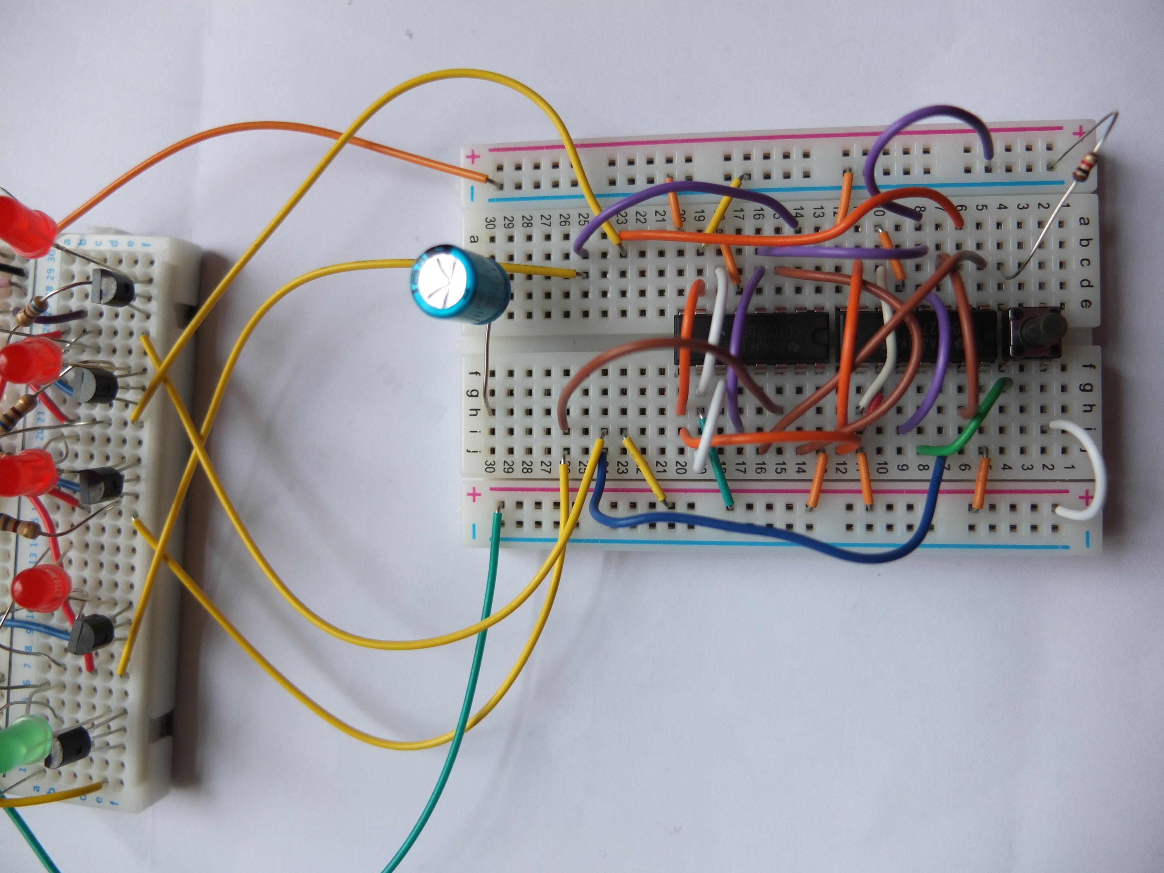 The second board you can see is the memory bank we just built. So the switch at the right of the small breadboard toggles the clock (clock is high when switch is pressed) and that is fed into one JK flip flop. The output from that is fed as the clock input to the second JK flip flop and so. This gives us 4 outputs which are counting through the binary numbers 0000, 0001 0010 …….. 1111.
When I first made the circuit I was surprised that the counter was counting down rather than up but creating a timing diagram (see below) showed me why that was the case. All I then did was keep the Q output as the next clock signal but use the Q-bar output from each of the flip flops as the actual output to pass to the memory bank.
With that working I could manually toggle the clock and see that I was sending a binary value to the memory bank and getting the state of the corresponding dip switch from the green LED. Now if we can extend that to reading bytes rather than bits and being able to execute different machine codes in different ways (not just LED on or off) we’re actually close to a basic computer!
Without the capacitor the initial state of the JK flip flops was unpredictable but with the capacitor properly connected the four LEDs come on consistently as an initial state so the first clock pulse gives us the 0000 value we want. A reset button would also be useful to get to that state whenever we wanted. The switch is also ‘bouncing’ at time so one or two binary states can apparently be skipped sometimes. However there are simple solutions to this problem – in particular the 555 chip which we’ll come to next.
Here’s the timing diagram for the flip flops in series. The binary values at the bottom should be read bottom up – ie 0000, 1111, 1110 etc. So you can see this counts down rather than up. Since each Q-bar is the inverse of its Q output using the Q-bar outputs counts up as required.
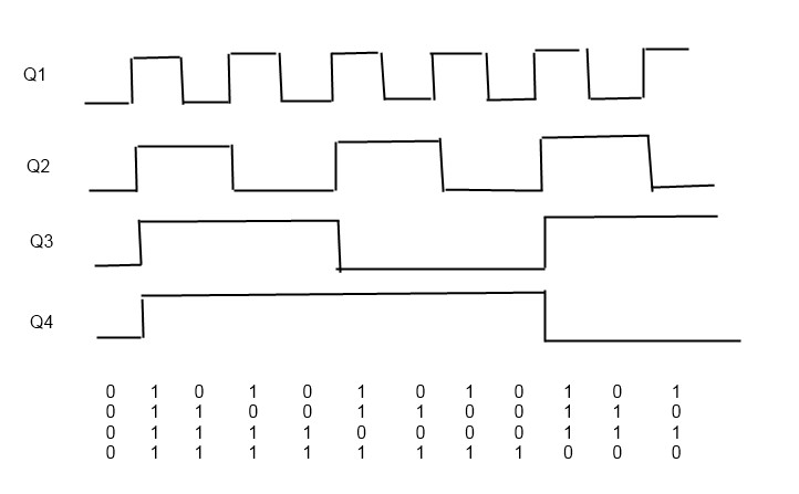 Interestingly if we had negative edge triggered JK flip flops this would have worked without the further complication of having to use Q-bar.
Footnote: I noticed that the bounce from the switch/button happened more when the corresponding dip switch was off so reduced the current through the button by using a larger resister there (470K instead of 1K). That did reduce the bouncing quite a bit but on applying power the circuit no longer had a reliable initial state. Increasing the capacitor (100 uF instead of 47uF) got me back to the initial state referred to above. I then removed the switch and set up a 555 astable circuit to give a clock pulse once a second or so and it stepped quite nicely through the 16 binary states without any skipping. The final version of this circuit can be seen on this page.
